Proteus
Graphical Language (
|
|
|
Figure 1.
|
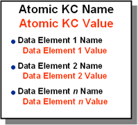
Data Elements
Data elements are depicted as rows within an AKC, below the name and value of the AKC. The name and value of the data elements are each in a separate row. The data element name is bulleted to distinguish each data element clearly from its adjacent ones. The order of the data elements has no significance from the perspective of an AKC’s functionality.
The data elements cannot be contained in PKCs or guidelines directly and cannot be linked by PALs.
Process Knowledge Component
The Process KC is
represented by a rounded rectangle – a rectangle in which each corner is a
smooth curve instead of being right-angled. Like the
Figure 2.
|
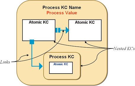
Nesting
The contained entities of a KC are shown nested within the icon of the container KC. If the container is a PKC, unlimited degree of nesting may be possible. The linking with PALs can only be done with KCs nested in a PKC at the same level.
The contained entities have to be depicted fully contained with the container KC icon i.e., a contained KC may not be shown to cross over the boundaries of the container KC icon. The developers may however create applications in which at a time only the partial contents of the KC are visible and others can be seen by scrolling within the KC. The nested entities may be hidden when the container KC is collapsed.
Activity Transition – Proteus Activity Links (PALs)
Within a process, workflow features like sequencing, co-occurrence and reiteration of activities can be shown by linking activities with Proteus Activity Links (PALs). The PALs denote how an activity is launched in relation to the launching or completion of another one. The PALs represented the edges of the directed graph of a PGL representation of a guideline while the KC icons form the vertices.
Each
The edges representing
|
Figure 3. The Proteus Activity Links (PALs) used in
|
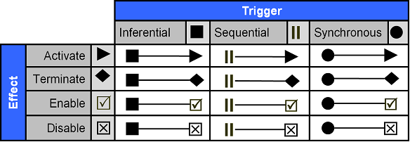
PAL
Trigger Types
The way the PAL is triggered determines the shape of the PAL’s trigger end, where it connects with the trigger KC. The triggers are of 3 types.
Sequential
Sequential
Inferential
Inferential
Synchronous
Synchronous
PAL
Effect Types
This is the resultant activity or the effect of the PAL on
the target KC. In
Activate
The Activate
Terminate
The Terminate
Enable
The Enable
Disable
The Disable
Types of PALs
Inferential Activate PAL
|
Figure 4. An example of Inferential Activate PAL. If the PKC,
"Risk of Infection" evaluates to true and if it is the trigger of
an Inferential Activate
|
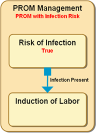
The Inferential Activate
Inferential Terminate
PAL
|
Figure 5. An example of Inferential Terminate PAL. The PKC, "Risk of Infection" evaluates to true, which causes the AcIT of its container PKC to not only trigger the PAL leading to the KC "Induction of Labor" but will also trigger an Inferential Terminate PAL which will stop the PKC, "Monitor for Labor Onset". The PAL has the optional label, “Infection Present è Stop Monitoring”. |
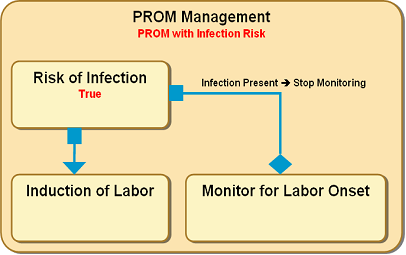
The Inferential Terminate PAL represents a trigger to stop the activity of a KC based on an inference taken within the container PKC within which the PAL exists along with its connected KCs. Its target KC is stopped as a result of the inference. This PAL terminates the target KC if the KC is in the ‘invoked’ state and has no effect on KCs in other states. The PGL icon representing this PAL is a directed edge from the trigger KC to the target KC, which is the KC to be stopped as a result of the inference. The trigger end of the link is a filled square whereas the target end is shaped like a rhomboid. This link may be read as "After A finishes, the execution of B is stopped based on an inference by the AcIT of the container X", where A is the trigger KC and B is the target and X is the container PKC in which the A, B and the PAL are contained. The PAL may have a label showing its name and condition(s) that lead to its triggering.
Inferential Disable PAL
|
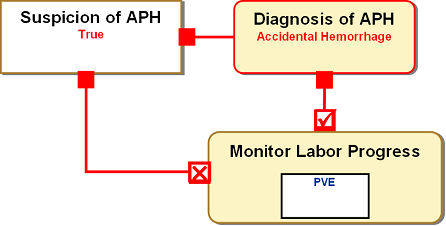
Figure 6. An example of Inferential Disable PAL. A PKC, ‘Suspicion of APH’
evaluates to true, which leads to triggering of a PKC, ‘Diagnosis of APH’
which evaluates to be “Under Investigation’. This triggers an Inferential
Disable PAL which connects the ‘Diagnosis of APH’ PKC to the ‘Monitor Labor
Progress’ PKC, disabling it, so that the ‘PVE’, which is a contained AKC in
it, is not triggered anymore. The PVEs (Per Vaginum Examinations) are not
to be performed any more until the cause of APH is established, as PVE is
potentially dangerous with certain types of APH. By disablement, not only
the ‘Monitor’ PKC will be brought to a stop now, but it will not be
activated again by any other PAL. Some other PAL (not shown here) will have
to later explicitly enable it again for it to have the ability to be
activated.
|
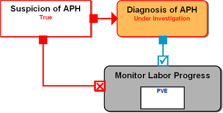
The Inferential Disable PAL represents disabling of a KC by an inference taken in the container PKC, so that any subsequent PAL cannot activate the KC. However, the disabled KC may be enabled later by an enabling PAL. The target KC has to be in enabled state for this to have effect on it, it has no effect on KCs in other states. The trigger end of the link is a filled square whereas the target end is a square with an X in it. This link may be read as "After A finishes, B is disabled based on an inference taken by the AcIT of the container X", where A is the originating KC and B is the target and X is the container PKC in which the A, B and the PAL are contained. The PAL may have a label showing its name and condition(s) that lead to its triggering.
Inferential Enable PAL
|
Figure 7. If the PKC, ‘Diagnosis of
APH’ evaluates to be “Accidental Hemorrhage”, it triggers an Inferential
enable PAL that connects to ‘Monitor Progress of Labor’, so that the
monitoring of labor can be resumed. Monitoring is necessary because vaginal
delivery is to be attempted aided by induction of labor. The PVEs which are
shown as contained KCs of the ‘Monitor’ KC may be performed again, since
there is no additional risk with Accidental Hemorrhage.
|
The Inferential Enable PAL represents enabling of a KC, if it is in disabled state, by an inference taken in the container PKC, so that a subsequent Activate PAL may activate the KC. The target KC has to be in disabled state for this to have effect on it, it has no effect on KCs in other states. The PGL icon representing this PAL is a directed edge from the trigger KC to the target KC, which is the KC to be enabled as a result of the inference. The trigger end of the link is a filled square whereas the target end is a square with a checkmark within it. This link may be read as "After A finishes, the execution of B is enabled based on an inference taken by the AcIT of the container X", where A is the originating KC and B is the target and X is the container PKC in which the A, B and the PAL are contained. The PAL may have a label that represents the inference that leads to its triggering.
Sequential Activate PAL
Some activities may be triggered without an inference deciding their activation – that the activation of the target KC must take place is predetermined if a preceding activity occurs. The Sequential Activate PAL allows representing such situations. This PAL activates the target KC if the KC is in the ‘enabled’ state, and either ‘not invoked’ state or ‘suspended’ state. The icon for the Sequential Activate PAL is an edge with its trigger-end shaped as 2 parallel bars perpendicular to the edge and the target-end shaped like an arrowhead. This link may be read as "after A is complete, B is started", where A is the trigger KC and B is the target.
Sequential Terminate PAL
The Sequential Terminate PAL is similar to previous PAL, except that the target KC is stopped if it is in active state. This PAL terminates the target KC if the KC is in the ‘invoked’ state and has no effect on KCs in other states. The icon for the Sequential Terminate PAL is an edge with its trigger-end shaped as a pair of parallel bars perpendicular to the edge and the target-end shaped like a rhomboid. This link may be read as "after A is over, B is stopped", where A is the originating KC and B is the target.
Sequential Disable PAL
The Sequential Disable PAL represents sequential disabling of a KC, so that any subsequent PAL cannot activate the KC. The target KC has to be in enabled state for this to have effect on it, it has no effect on KCs in other states. The icon for the Sequential Disable PAL is an edge with its trigger-end shaped as two parallel bars perpendicular to the edge and the target end is a square with an X within it. This link may be read as "after A is over, B is disabled", where A is the originating KC and B is the target.
Sequential Enable PAL
The Sequential Enable PAL represents sequential enabling of a KC, if it is in the disabled state, so that a subsequent PAL can activate the KC. The target KC has to be in enabled state for this to have effect on it, it has no effect on KCs in other states. The icon for the sequential enable PAL is an edge with its trigger-end shaped as two parallel bars perpendicular to the edge and the target end is a square with a checkmark within it. This link may be read as "after A is over, B is enabled", where A is the originating KC and B is the target.
Synchronous Activate PAL
This Synchronous Activate PAL allows representing situations where two or more activities are initiated simultaneously. Besides synchronous onset the link does not imply any other semantic connection between the two. KCs may have more than one synchronously linked targets. All such KCs linked by synchronous activate PALs are launched together. This PAL activates the target KC if the KC is in the ‘enabled’ state, and either ‘not invoked’ state or ‘suspended’ state.
An edge connecting 2 KCs with a filled circle at its trigger-end and an arrowhead at its target end represents this link. This link may be read as “with the launch of A, launch B and launch C”, where A is the originating KC and B and C are each respectively targets of 2 synchronous activate PALs from A. To allow a more readable layout in a PGL representation of a process, the KCs may be chained with synchronous activate links. E.g. if after termination of a KC A, the KCs B & C are to be launched sequentially, they may be represented by a Sequential Activate PAL from A to B and another from A to C. However if this representation leads to a messy diagram, A may be linked with B with a Sequential Activate PAL and B to C, with a Synchronous Activate PAL. Though the 2 forms are not strictly same, semantically, in most situations this alternative representation will be acceptable. The Synchronous Activate PAL may also be used, if more than one KCs have to be launched based on the same inferencing. The inferencing may then be created for only one KC and all the other KCs are linked with it by Synchronous Activate PALs, rather than authoring the same inferencing for all KCs separately.
|
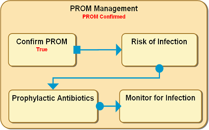
Figure 8. In a process representing management of PROM, after the PKC, "Confirm PROM" is evaluated to be true, another PKC, "Risk of Infection", connected to it by an inferential activate PAL is triggered. However, along with evaluation of risk of infection, the prophylactic antibiotics, and monitoring for infection have also to be started. Therefore, the “Evaluate risk of infection” is connected to another PKC, “Prophylactic Antibiotics” by a Synchronous Activate PAL, and another Synchronous Activate PAL connects the latter to a PKC, “Monitor for infection”. When “Evaluate for infection” PKC is triggered, “Prophylactic Antibiotics” and “Monitor for infection” are simultaneously triggered too. |
Synchronous Terminate PAL
This PAL represents situations where with launch of one activity, another activity has to be simultaneously stopped. This PAL terminates the target KC if the KC is in the ‘invoked’ state and has no effect on KCs in other states.
An edge connecting 2 KCs that has a filled circle at its start and a rhomboid at its end represents this PAL. This link may be read as "With launch of A, stop B", where A is the originating KC and B is the target KC. Unlike the Synchronous Activate PAL this cannot be used to chain KCs because the synchronicity links are always with the activation of the originating KCs and once they have been stopped by a prior link they cannot launch or stop another activity.
Synchronous Disable PAL
The Synchronous Disable PAL represents disabling of a KC simultaneously with the launch of another KC, so that any subsequent Activate PAL cannot launch it. The target KC has to be in enabled state for this to have effect on it, it has no effect on KCs in other states. An edge connecting 2 KCs that has a filled circle at its trigger end and a square with an X in it at its target end represents this PAL. This link may be read as "With launch of A, disable B", where A is the originating KC and B is the target KC.
Synchronous Enable PAL
The Synchronous Disable PAL represents enabling of a KC simultaneously with the launch of another KC, so that any subsequent Activate PAL may launch it. The target KC has to be in enabled state for this to have effect on it, it has no effect on KCs in other states. An edge connecting 2 KCs that has a filled circle at its trigger end and a square with a checkmark in it at its target end represents this PAL. This link may be read as "With launch of A, enable B", where A is the originating KC and B is the target KC.
Delay
Delay is an attribute of the PALs and Conduits (described below). It is the representation of the duration of wait between triggering of a PAL and triggering of its effect. A delay on a PAL signifies the stalling of the thread of execution for the duration specified. Delay is also useful in specifying the frequency of reiterative PALs. For sequential and synchronous PALs the delay is immutable at the runtime, i.e. the delay is specified at the time of authoring and does not change during execution. So, even if for all practical purposes a PAL may be sequential but if the delay needs to be changed, an inferential PAL has to be used. For the inferential PALs, the AcIT of the container may modify it at the runtime. The AcIT therefore does not only specify which inferential PAL has to be triggered by it but may also specify the delay associated with the PAL. If the PAL does not have an author-specified delay and if the AcIT also does not have the delay output, it results in immediate triggering of the inferential PAL.
Synchronous links also have delays. The synchronous links with delay implies that they are triggered simultaneously with the trigger KC but get activated after the delay is over. Incidentally, this is how a pair of synchronously linked KCs differs from a pair of unlinked KCs at the same nesting level. For the iteration links the frequency can be converted to delay and vice versa (see reiteration, below).
Reiteration
There are many situations in which an activity has to be depicted to repeat more than once. It is economical to represent such activities only once and designate it as reiterative. At the runtime, each iteration reflects a new instance of the activity.
Reiteration is frequently required for monitoring kind of activities when the same parameters have to be checked repeatedly. To depict such reiterative activities, the Sequential Activate or Inferential Activate PALs described above may be used. In PGL, the PAL used to depict iteration has the same KC as its trigger and target.
Types of Reiterations
Depending upon whether the frequency or the number or iterations is specified or not, the reiteration in Proteus can be of the following types:
- Frequency specified, number of iterations specified. E.g., do ‘Urine Sugar’ 1/hour, 3 times
- Frequency specified, number of iterations not specified. This implies that some external PAL or the change of the state of the container will eventually interrupt the iterations. e.g., a reiterative KC “Fetal Heart Rate” is specified to repeat 1/15 minutes. This reiterative activity will be stopped when he KC, “Monitoring Labor” results in a value “Delivered” and which is the trigger of an has an Inferential Terminate PAL which has its target the “Fetal Heart Rate” KC.
- Frequency not specified, number of times specified. This implies that the activity is to be repeated the specified number of times without any delay between the reiterations. E.g., do ‘Aspiration of Gastric Contents’ 3 times in succession.
- Frequency not specified, number of times not specified. This implies repetition of the activity precisely once more and immediately after the first iteration is over
Sequential Reiteration: Reiterative Sequential PAL
Sequential link based reiteration is used when the frequency/delay or the number of iterations are known at the author time and do not change at the run time. The number of iterations can be directly specified but the frequency is established by the specifying the delay for the PAL.
These links have the attribute, iteration specified to represent the number of times that link has to be fired, and the number of iterations to be performed. There is an attribute, iteration count too, which keeps the track of runtime firing of the link. The KC involved in a reiteration also keeps a record of its own reiterations. This may appear to be a redundancy but there may be situations where both may be instantiated separately. The delay attribute of the PAL represents the frequency of the reiteration specified. The author may specify frequency instead of delay, because it is common in the clinical parlance for specifying reiterative activities. The frequency is converted to delays as follows
T - TKC = DELAY
Where:
T = duration for each iteration based on frequency
TKC = duration for execution of the KC
An example:
If the frequency specified is 3/hour and the KC takes 1 minute to finish execution
20 minutes - 1 minute = 19 minutes
The delay for the link is set to 19 minutes
The value of time to live/execute, which is an attribute of KC, should not exceed the time for one iteration. The editing facility of the Proteus applications has to ensure this.
When a KC that is in reiteration finishes execution, the container PKC checks the number of time its reiterative PAL has completed the reiterations and if it has reached the designated number of reiterations for it. If it is yet to run the specified number of reiterations fires it off yet again.
If during execution, the KC does not finish within the time specified for it, and this leads to the duration for the iteration to exceed the specified duration, the author may specify what should be done. The options in this situation are, to allow the reiterations to continue, stop them, or the delay for the next iteration of the PAL is reduced to keep the duration for the entire set of iterations as specified, or to ask the user. If the user is asked at the run time, he/she is offered the first three choices.
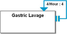
In PGL, the frequency of iteration per unit of time may optionally be displayed within the space between the reiterative PAL and the KC. Also optionally, the total number of iterations may be depicted. The format of this label is Frequency/Time unit: n, where n is the number of maximum iterations for the KC (e.g. 3/day: 6). The time unit may be any standard time unit.
|
Figure 9. An AKC “Gastric Lavage” in this PGL representation is specified to sequentially reiterate with the frequency of 4 times per hour for total of 4 times. |
Inference Based Reiteration– Reiterative Inferential PAL
When a reiteration is dependent on any kind of logic (e.g., “repeat monitoring if not delivered”), the PAL is fired based on that logic alone. This means that there may be situations when the link may not get fired at all after the first execution of its KC is complete. The inferential reiterative PAL does not have a total number of iterations specified. The delay (frequency) may be specified by the author, but the AcIT of the container PKC may override it at the runtime.
Inferential links are to be used even if no logic other than change of frequency/delay is required (which means if the PALs are essentially sequential links in almost all respects except but if their frequency or the number of times that they are to execute undergoes a change at the execution time), inferential reiterative PALs have to be used instead. The AcITs of the container PKC can specify the delays associated with the inferential PALs besides determining if they are to be launched or not. If the AcIT doesn’t provide the delay output, the author-specified delay is applied, and if the latter is also not specified the PAL is launched again immediately.
Non uniform frequency of Iterations
Known non uniform frequency of iterations
There are situations where activities have to be done repeatedly but their frequency is not always uniform. E.g. do monitoring at interval of 5 days, 10 days, 1 month, 3 months and 1 year. An ordered collection of sequential iteration PALs with each PAL having a different delay is used to achieve this. Only in the reiteration situation, more than one PAL of the same type with the same pair of trigger and target KCs are allowed. For economy of representation in PGL, this collection of PALs may be shown as a single PAL with the annotation specifying the different delays for each iteration.
Unknown non uniform frequency of iterations
When it is not known a the author time, at what frequency should the iteration occur, the AcIT achieves the desired frequency at the runtime, by setting the delays for the inferential PAL at each iteration.
Conduit
In contrast to the KCs, which also serve as representations for domain activities, Conduit is a pure workflow element. Like KC the conduit is also a reusable component.
The main responsibility of a conduit is to allow activation by one or more incoming links, perform some temporal function (delay or sequencing of activations), and then let the process continue to one or more outgoing links. The various incoming PALs may provide the activation impulse at different time points but all the outgoing PALs are activated simultaneously. The incoming PALs can only be of the activation type. The outgoing PALs can only be sequential, each of which may have a delay of their own. Conduit is a pure design time specification and its behavior is not altered by any event during the run time. Therefore its functioning is not controlled by any inferencing tool. The conduit may also be associated with a delay.
In PGL, the conduit is represented as a truncated triangle (trapezoid), with the narrower side in the direction of the process flow. The broader side receives the incoming PALs and the outgoing PALs emerge from the narrower side of the conduit. The conduit may optionally show its type and any delay that is associated with it in a label. Since the incoming PALs are always are equivalent to activation target types and the outgoing ones are always sequential trigger types, the incoming PALs do not show the usual target end and the outgoing PALs do not show trigger ends as they do when they are connecting to the KCs.
Please note that only in rare circumstances will conduits be required in clinical process representations. The concept of conduit was included in PGL and Proteus to allow comprehensive workflow semantics to be represented.
Types of Conduits
A conduit has to be specified to be of merger, or synchronizer type. The merger may be specialized as a sequencer and the synchronizer may be specialized as n-of-m type conduit. The conduit types are described here:
Merger
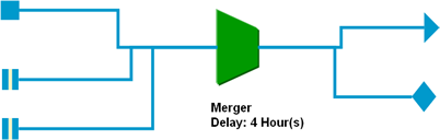
This conduit has at least 2 incoming PALs (2-*), and has one or more outgoing PALs (1-*). For activation from each incoming PAL, all outgoing PALs are triggered. If there is a delay associated with the conduit then it is applied after each of the activations is received and before the outgoing PALs are triggered. Each conduit has to be specified to be either a merger conduit or a synchronizer conduit.
|
Figure 10. Merger Conduit with a delay of 4 hours. For each activation received both the outgoing PALs are triggered. |
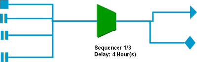
Sequencer
Sequencer is a specialized type of merger. This allows specifying frequency of activation impulse conduction across it. For example, a sequencer may specify 1/3 as its frequency, which will allow only activation by every third PAL that is its input to be passed on to the outgoing PALs.
|
Figure 11. A Sequencer Conduit specifying that only one out of every three activations is transmitted across it. It has a delay of 4 hours. |
Synchronizer
The outgoing PAL(s) are triggered only when all the incoming impulses have been received. In contrast to the merger types of conduits, the synchronizers only transmit activation once during the life of an instance. If there is a delay associated with the conduit then it is applied after all the impulses are received and before the outgoing PALs are triggered. Each conduit has to be specified to be either a merger conduit or a synchronizer conduit.
|
Figure 12. A Synchronizer Conduit with a delay of 1 hour. When all 4 of the incoming activations have been received both the outgoing PALs will be triggered. |

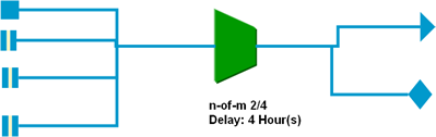
N-of-M Processing
This is a special type of synchronizer conduit. The author can specify the number of incoming links that provide the activation impulse before the outgoing links are fired. If the actual incoming PALs are less than the specified N, then the conduit never gets fired. The authoring tools may have mechanisms to warn the author about such a situation.
|
Figure 13. An n-of-m type Conduit with a delay of 1 hour. Only when 2 activations out of the possible 4 have been received will the 2 outgoing PALs be triggered. |
Split representation by Conduit
The conduit represents a split by having more than one outgoing PALs. If there is only one outgoing PAL, the conduit doesn’t represent a split.
Conduit Delay
As described previously, each conduit may also have a delay specified by its author and is applied before the outgoing PALs are triggered.
Advantages of PGL
The Proteus Graphical Language has the following benefits:
- PGL can display the semantics of workflow that clinicians can understand. This has been tested in a limited way with clinicians. With brief training the clinicians can understand guidelines and activities represented in PGL and can also depict new processes with the language. We aim to conduct a more rigorous, formal testing of PGL’s ability as a representation, in our future efforts.
- PGL is suitable for editing. The same low-coupling approach of components is utilized in the PGL as in Proteus information model, which makes editing and reuse easier.
- PGL is completely compliant with the Proteus information model, which allows creation of tools in which authoring and modification can be done with the graphical icons in an application, which can change the underlying information entities.
- PGL can also be used in an application to depict what has transpired with a particular patient with a condition and what are the possible pathways for him/her within a guideline. This is possible by utilizing features like color codes and other adornments to display the states of different PGL elements. This is of particular value when a large guideline is being traversed and one has to take an overview of situation intermittently.
What PGL does not show
As said earlier, the PGL is by design a parsimonious representation, to facilitate quick learning by the clinicians. For instance, the PGL does not specify that the inference tools, the permissible values, attached information (website, documents), administrative information (who, where) be shown. However, the developers are free to utilize adornments and other user interface gambits within an application to show these kinds of informations. The developers are only expected to not violate the described specifications for PGL for creating their own approaches.
UML Activity Diagram and PGL
PGL has been endowed with several notational elements of the UML Activity diagrams. The key similarities and differences are highlighted in this section. The activities have icons in both notations, though PGL also distinguishes between processes and atomic activities and activity diagram notation does not. Edges are used to denote activity transitions in both notation systems. However, in PGL there are several types of edges with precise definitions. This allows increased expressivity for defining clinical processes and activities. Both notation systems support nesting of activities. There is no decision icon in PGL because the inferential PAL emerging from a KC or a conduit implies decision based action transition. Similarly, there are no notation elements in PGL for initial and final activities – the workflow specification makes these explicit. Some of the functionality for forking and joining is made explicit by how the PALs are connected with KCs or conduits. Conduits also provide some of these functionalities. In PGL, there are no equivalents for activity diagram elements of send, receive, and object.
UML State Diagram for KC
|
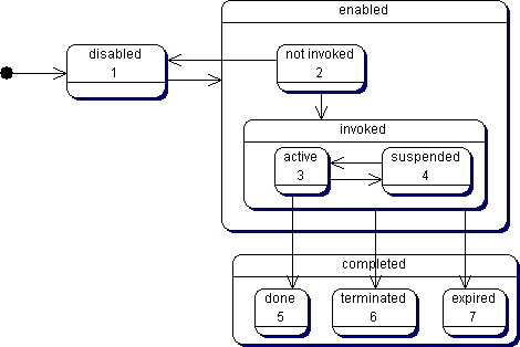
Figure 14. A KC can only be in one
of the seven states at a time as it passes through its life cycle. Some of
these states are substates of a other higher level states, which means that
when a KC is in a particular state it can be also be in certain
superstates. The UML state diagram shows the various states and the
superstates.
|